Key Takeaway
The first thing an I2C/SPI/UART interview question checks is the number of wires and whether the protocol is synchronous or asynchronous. I2C uses 2 wires (SDA, SCL) and is synchronous; SPI uses 4 wires (SCLK, MOSI, MISO, CS) and is synchronous; UART uses 2 wires (TX/RX, plus GND) and is asynchronous. In an interview, the key is to explain this structural difference first, then move on to device-selection method, speed, and typical use cases.
This post organizes the core concepts and answer points for I2C, SPI, and UART from the perspective of preparing for embedded BSP/firmware job interviews.
I2C vs SPI vs UART: How many wires, and sync or async?
One-line answer: I2C = 2 wires (SDA, SCL), synchronous · SPI = 4 wires (SCLK, MOSI, MISO, CS), synchronous · UART = TX/RX 2 wires (+ GND), asynchronous
- Synchronous means a clock line is sent along with the data; asynchronous means there is no clock line, and both sides agree on the same baud rate in advance.
- A frequent interview point is that I2C requires an open-drain configuration with pull-up resistors.
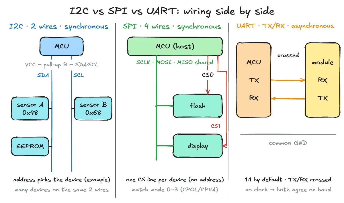
- Comparing wire count, clock, and duplex mode across the three buses:
| Item | I2C | SPI | UART |
|---|---|---|---|
| Wire count | 2 wires (SDA, SCL) | 4 wires (SCLK, MOSI, MISO, CS) | 2 wires (+GND) (crossed TX, RX) |
| Sync/async | Synchronous (has clock) | Synchronous (has clock) | Asynchronous (no clock) |
| Duplex | Half-duplex | Full-duplex | Full-duplex |
How do speed, addressing, and multi-device wiring differ?
One-line answer: I2C groups multiple devices onto 2 wires using addresses, SPI picks each device with its own CS line and shifts data on a shared clock, and UART is a 1:1 link where both sides agree on a baud rate.
- I2C selects a device by address (7 bits, which “can be expanded to get a 10 bit I2C address”). Multiple devices can share the same 2 wires. The Rd/Wr bit (Rd=1, Wr=0) distinguishes read from write, and A/NA (ACK/NACK) confirms the response. Speed is defined at the mode-name level (Standard-mode, Fast-mode, High-speed mode); the Linux kernel docs describe it as “typically up to 400 kHz, high speed modes up to 5 MHz.” (Example addresses: 0x48 / 0x68)
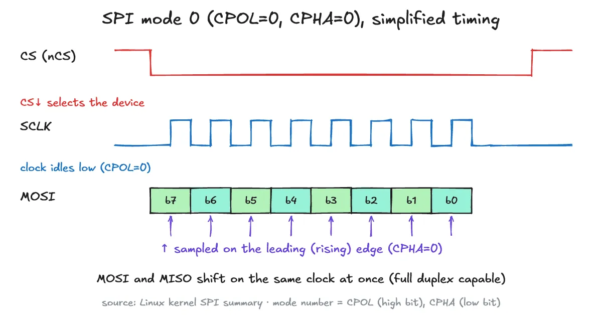
- SPI has no addressing, so each device gets its own CS (Chip Select) line, while SCK, MOSI, and MISO are shared. There are clock modes 0–3, where CPOL is the initial clock polarity and CPHA is the phase (CPHA=0 samples on the leading edge); mode 0 means CPOL=0, CPHA=0. SPI is a “simple de facto standard, not complicated enough to acquire a standardization body,” and targets “only rarely support any kind of automatic discovery/enumeration.” Speed is set by the chip and board datasheets; the kernel docs only describe SCK as “often on the order of 10 MHz.”
- UART is basically a 1:1 link, with start/stop bits delimiting each frame. Both sides must use the same port parameters (word length, parity, stop bits, baud rate, as listed in the kernel serial driver docs), so speed is matched by configuring the same baud rate (e.g., a conventional value such as 115200).
- A detailed comparison by communication characteristic:
| Item | I2C | SPI | UART |
|---|---|---|---|
| Device selection | Address (7-bit, extendable to 10-bit) | CS (Chip Select) line | Basic 1:1 link |
| Multiple devices | Shared on 2 wires | Added via extra CS lines | 1:1 |
| Response confirmation | ACK/NACK | None | None |
| Speed determined by | Communication mode spec | Chip/board limits | Agreed baud rate on both sides |
Sensors, flash, or a debug console — which do you pick? An interview answer framework
One-line answer: Use I2C for sensors where you need to save pins, SPI for flash that needs fast continuous transfer, and UART for boot logs or simple communication.
- I2C use cases: connecting multiple sensors or EEPROMs while saving pins.
- SPI use cases: fast, continuous transfers such as SPI flash, displays, and ADCs. Per the kernel docs, every MMC/SD card supports SPI, and some PC hardware uses SPI flash for BIOS code.
- UART use cases: boot logs, debug consoles, and module communication such as GPS/BT.
- Interview answer template: “First mention the wire count and sync/async difference, then compare device-selection method and speed, and finally walk through the representative use case for each protocol in order.”
Interview one-liner: First point out the structural difference — I2C is 2-wire synchronous with addressing, SPI is 4-wire synchronous with CS, UART is 2-wire asynchronous with a baud rate — then follow up with each protocol’s typical use: pin-saving, speed, or simple communication.
Related posts: Interrupt vs Polling: How to Choose in an Embedded Interview · What Is DMA? How It Differs from CPU Copy and How to Answer in Embedded/Firmware Interviews
Reference docs: I2C summary · I2C protocol · SPI summary · Serial driver API
What are the frequently confused questions (FAQ)?
Q. Why does I2C communication need pull-up resistors?
I2C lines are open-drain: devices can only pull a line low, so an external pull-up resistor is needed to bring it back high when released.
Q. What symptom appears if the SPI mode doesn’t match?
Data is sampled on the wrong edge, so bits can look shifted or corrupted. Check CPOL/CPHA against the chip datasheet’s timing diagram.
Q. If UART data comes out as garbage, what should you check first?
Check both sides’ baud rate settings, the shared GND connection, and whether TX and RX are correctly crossed.