The core difference between open-drain and push-pull GPIO outputs lies in whether the output stage actively drives the line to both high (1) and low (0) logic levels, or actively drives only one level and releases the line to a high-impedance (Hi-Z) state for the other. Based on the Linux kernel GPIO driver and consumer interface documentation along with an illustrative Python logic-level model, this post explains how both output stages work and why pull-up or pull-down resistors are required.
Key Takeaways
A push-pull output uses a CMOS totem-pole stage with two transistors (P-MOS and N-MOS) to actively drive a line both high (1) and low (0). An open-drain output disables the P-MOS transistor and only drives the line between GND (low) and high impedance (Hi-Z), requiring a pull-up resistor to complete the circuit and bring the released line high instead of leaving it floating. This makes open-drain suitable for multi-device inverse wire-OR shared buses and level-shifting to a higher external VDD, while Linux kernel gpiolib configures or emulates open-drain via GPIO_OPEN_DRAIN and GPIOD_OUT_*_OPEN_DRAIN.
What is the difference between open-drain and push-pull?
One-line answer: Push-pull actively drives both high (1) and low (0) using two transistors, whereas open-drain only actively drives low and switches to high impedance (Hi-Z) instead of driving high.
Push-pull (totem-pole) output stage
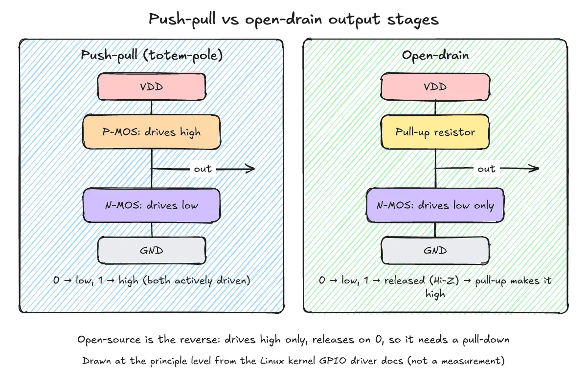
According to the Linux kernel GPIO Driver Interface documentation, integrated electronics commonly implement an output driver stage as a CMOS totem-pole consisting of one N-MOS and one P-MOS transistor. One transistor drives the line high (1) and the other drives the line low (0); this is called a push-pull output. When both switches in the totem-pole are closed, the output actively drives both logic levels.
Open-drain and open-source output stages
Opening one of the switches disables half of the totem-pole, presenting high impedance (tristate) instead of actively driving that rail. The Linux kernel documentation defines the two resulting modes as follows:
- Open-drain (CMOS) / open-collector (TTL): By disabling the P-MOS transistor, the line is not actively driven high; the drain or collector is provided as the output, driving the line between GND (low) and high impedance.
- Open-source: By disabling the N-MOS transistor, the line is not actively driven low; the output is driven between VDD (high) and high impedance.
What does high impedance (Hi-Z) mean and why is a pull-up resistor needed?
One-line answer: High impedance means the output transistor releases the line without driving it, so a pull-up resistor is needed to complete the circuit and pull the line high instead of leaving it floating.
Floating lines and the role of a pull-up resistor
Open-drain and open-source lines do not actively drive their output high (for open-drain) or low (for open-source); instead, they switch the output to a high-impedance value. When the transistor is not conducting, it presents a high-impedance (tristate) state to the external rail. If no pull resistor is attached, a released line has no defined logic level and is left floating.
Therefore, an open-drain output requires a pull-up resistor on the outgoing rail to complete the circuit. This pull-up resistor makes the line tend toward a high level unless one of the transistors on the rail actively pulls it down to GND.
Open-source with pull-down resistors, board resistors, and software control
Conversely, when the N-MOS transistor is disabled so the output is driven between VDD and high impedance (open-source), a pull-down resistor is required on the rail to complete the circuit and pull the released line low.
As noted in the Linux kernel documentation, in discrete designs a pull-up or pull-down resistor is simply soldered onto the circuit board. A GPIO line may also offer software-controlled pull-up and pull-down resistors through the .set_config() callback. On its own, that interface can only switch pull-up or pull-down on and off without knowledge of the resistance; selecting different resistance values requires a combined GPIO chip and pin controller setup.
What happens when multiple open-drain outputs share a single line?
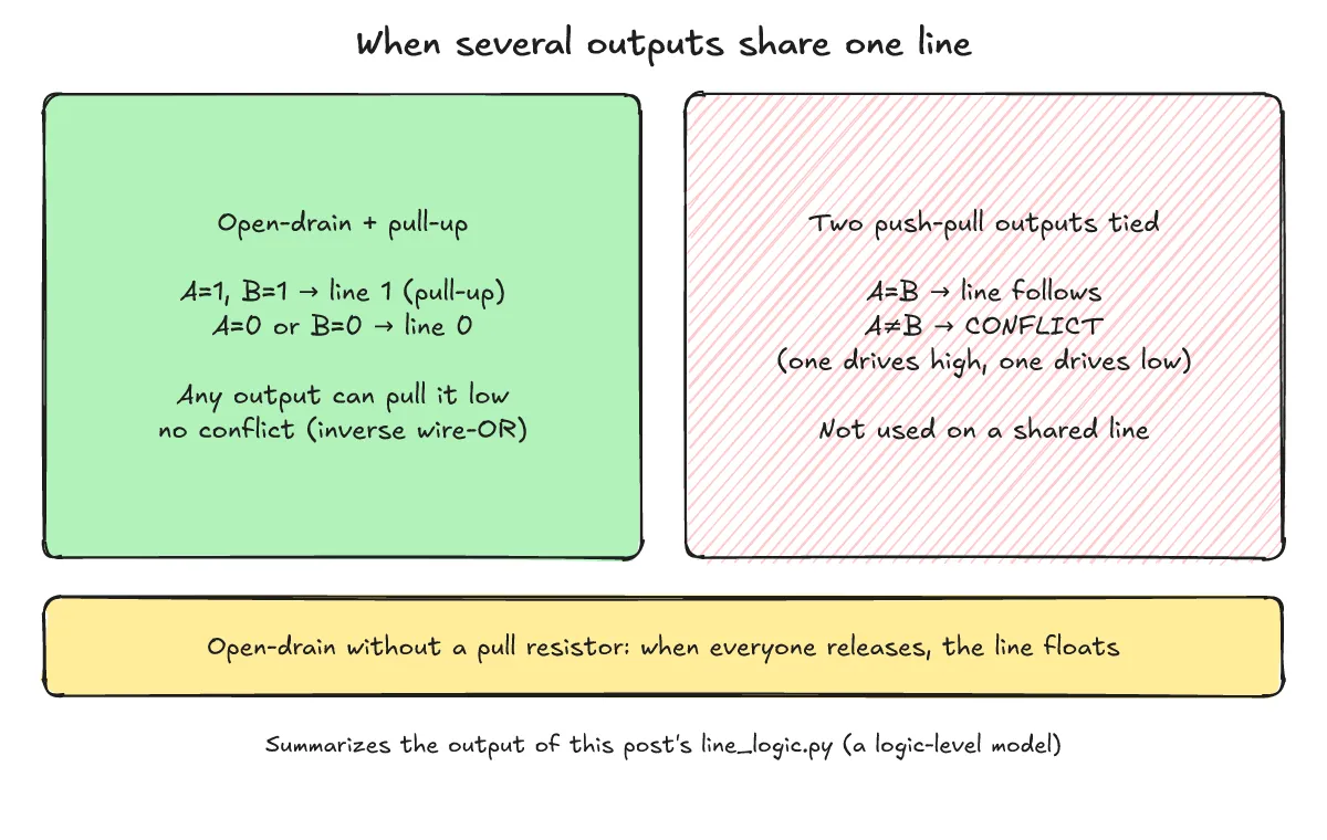
One-line answer: It forms an inverse wire-OR bus where any output pulling low drives the shared line low, and the line goes high via the pull-up resistor only when all outputs release it to Hi-Z.
Principle of inverse wire-OR
The Linux kernel GPIO Driver Interface documentation highlights inverse wire-OR on an I/O line as one of the two primary use cases for open-drain. It allows any driving stage on the line to pull the line low even while other outputs connected to the same line are simultaneously outputting a logical high (high impedance). As the documentation notes, a classic special case of this is driving the SCL and SDA lines of an I2C bus, which is by definition a wire-OR bus equipped with pull-up resistors.
Shared line states in a logic-level model (line_logic.py)
The script line_logic.py below (run with Python 3.13) is a logic-level model for illustration only, not a circuit simulation or hardware verification. It shows what logic state a shared line settles to under open-drain and push-pull outputs:
# Logic-level model only (not a circuit simulation): what level does a shared line settle to?
# Each output is "low" (drives 0), "high" (drives 1) or "z" (released / high impedance).
from itertools import product

def resolve(outputs, pull):
    drives = {o for o in outputs if o != "z"}
    if drives == {"low", "high"}:
        return "CONFLICT (one drives high, one drives low)"
    if drives:
        return "0" if "low" in drives else "1"
    return {"up": "1 (pull-up)", "down": "0 (pull-down)", None: "floating"}[pull]

def open_drain(value):          # 0 -> pull the line low, 1 -> release it
    return "low" if value == 0 else "z"

def push_pull(value):           # 0 -> drive low, 1 -> drive high
    return "low" if value == 0 else "high"

print("open-drain, two outputs, pull-up")
for a, b in product([0, 1], repeat=2):
    print(f"  A={a} B={b} -> line {resolve([open_drain(a), open_drain(b)], 'up')}")

print("open-drain, both released, no pull resistor")
print(f"  A=1 B=1 -> line {resolve([open_drain(1), open_drain(1)], None)}")

print("push-pull, two outputs on one line")
for a, b in product([0, 1], repeat=2):
    print(f"  A={a} B={b} -> line {resolve([push_pull(a), push_pull(b)], None)}")
Running python3 line_logic.py produces the following output:
open-drain, two outputs, pull-up
  A=0 B=0 -> line 0
  A=0 B=1 -> line 0
  A=1 B=0 -> line 0
  A=1 B=1 -> line 1 (pull-up)
open-drain, both released, no pull resistor
  A=1 B=1 -> line floating
push-pull, two outputs on one line
  A=0 B=0 -> line 0
  A=0 B=1 -> line CONFLICT (one drives high, one drives low)
  A=1 B=0 -> line CONFLICT (one drives high, one drives low)
  A=1 B=1 -> line 1
In the first block, two open-drain outputs (A and B) share a line with a pull-up resistor: whenever either output pulls low (A=0 B=1 or A=1 B=0), the line settles to 0 without conflict, and only when both release the line (A=1 B=1) does the pull-up bring it to 1 (pull-up). In the second block, when both outputs release the line with no pull resistor attached, the line is left floating.
When is push-pull used and why are push-pull outputs not wired together directly?
One-line answer: Push-pull is used when a single output actively drives both high and low, and wiring two push-pull outputs together causes a conflict if one drives high while the other drives low.
Drive conflict between two push-pull outputs
If two push-pull outputs are tied together on the same line and drive opposite logic levels, they fight each other—one actively drives the line high while the other actively drives it low. In the third block of the line_logic.py output above, both A=0 B=1 and A=1 B=0 result in CONFLICT (one drives high, one drives low). This is why push-pull outputs are not wired together on a shared line.
Use on unidirectionally driven lines
When each line is driven by a single output rather than shared among multiple drivers, push-pull drives both high and low levels directly without needing an external pull resistor. Buses where a single device drives each signal line in a fixed direction, such as SPI, typically use push-pull outputs.
How is open-drain used for level-shifting?
One-line answer: Because the output transistor does not actively drive high, connecting the pull-up resistor to a higher external VDD rail shifts the line’s high logic level up to that external VDD.
Setting the high level via external pull-up VDD
The other primary use case for open-drain described in the Linux kernel GPIO Driver Interface documentation is level-shifting: reaching a logical level higher than that of the silicon where the output stage resides.
Just like inverse wire-OR, level-shifting requires a pull-up resistor on the line. When the open-drain transistor releases the line, the level on the line goes as high as the VDD connected to the pull-up resistor, which may be higher than the level of the transistor’s own rail—thereby shifting the high logic level to that higher VDD.
How is open-drain configured in Linux GPIO?
One-line answer: Linux kernel gpiolib configures hardware via GPIO_OPEN_DRAIN and GPIOD_OUT_*_OPEN_DRAIN flags and the gpio_chip .set_config() callback, or emulates open-drain by switching the line to input mode if hardware lacks native capability.
Driver configuration (.set_config) and input-mode emulation
According to the Linux kernel documentation, some GPIO hardware is hard-wired as open-drain or open-source with only a single transistor, while other hardware is software-configurable by flipping a register bit. Configurable drivers implement the .set_config() callback on gpio_chip in response to the GPIO_OPEN_DRAIN or GPIO_OPEN_SOURCE flags passed from a machine file or hardware description.
If the GPIO hardware cannot perform open-drain natively, kernel gpiolib emulates it: for an output value of 0 it drives the line low as usual, and for an output value of 1 it switches the line to input mode. Because input mode is equivalent to high impedance, this behaves identically from an electrical standpoint apart from possible glitches while switching modes (and the same principle applies to open-source emulation). For user-space control of Linux GPIO character devices, see libgpiod: working with GPIO lines on Linux.
Consumer flags and gpiod_set_value behavior table
In the Linux kernel GPIO Descriptor Consumer Interface, the flags GPIOD_OUT_LOW_OPEN_DRAIN and GPIOD_OUT_HIGH_OPEN_DRAIN enforce that a line is electrically used with open-drain. These flags are used where open-drain is mandatory, such as I2C; if open-drain is not already configured in the hardware mappings, it is enforced anyway with a warning.
The table below from the consumer documentation shows how gpiod_set_value() maps logical values to physical line states for open-drain and open-source lines:
| Configuration | gpiod_set_value(desc, 0) | gpiod_set_value(desc, 1) |
|---|---|---|
| Open drain | low | high impedance |
| Open source | high impedance | high |
The consumer documentation also notes that when reading an output line, the returned value will not always match the specified output value because of issues including open-drain signaling.
Connection to bus protocols
How an open-drain wire-OR shared bus leads to specific serial bus standards is covered in What is the difference between I2C, SMBus and I3C?.
For a broader overview of common serial buses, see I2C, SPI and UART basics.
What are the frequently asked questions (FAQ)?
One-line answer: Here are three common questions covering open-drain output values versus actual line levels, hardware emulation, and open-source outputs.
Why does gpiod_set_value(desc, 1) on an open-drain line set high impedance instead of driving high, and why can reading the output line differ from the set value?
As explained in the Linux kernel GPIO consumer documentation, open-drain lines never actively drive their output high; setting 1 switches the output to high impedance. Because another device on the shared rail may be pulling the line low during open-drain signaling, reading the output line will not always match the output value requested by this consumer.
How does Linux gpiolib emulate open-drain when the GPIO hardware cannot do it natively?
When hardware cannot do open-drain directly, gpiolib drives the line low as usual for value 0, and switches the line to input mode for value 1. Since input mode is equivalent to high impedance, this achieves the same electrical behavior apart from possible glitches when switching modes.
What is the difference between open-drain and open-source outputs, and which pull resistor does each require?
In a CMOS totem-pole stage, disabling the P-MOS transistor yields an open-drain output driven between GND (low) and high impedance, whereas disabling the N-MOS transistor yields an open-source output driven between VDD (high) and high impedance. Completing the circuit requires a pull-up resistor on an open-drain rail and a pull-down resistor on an open-source rail.
What related posts are worth reading?
One-line answer: Here are related posts covering Linux GPIO control and serial bus basics.
- libgpiod: working with GPIO lines on Linux
- I2C, SPI and UART basics
- What is the difference between I2C, SMBus and I3C?
What are the sources?
One-line answer: This post references the official Linux kernel GPIO driver and consumer interface documentation.
- Linux kernel docs: GPIO Driver Interface (checked 2026-11-04)
- Linux kernel docs: GPIO Descriptor Consumer Interface (checked 2026-11-04)