Understanding the difference between I2C, SMBus and I3C comes down to what electrical, timing, and command rules SMBus tightens on top of the baseline two-wire I2C bus, and how MIPI I3C redesigns addressing, interrupts, and line driving while remaining backward compatible with legacy I2C targets. Based on the SMBus Specification 3.3.1, the Linux kernel documentation, and the MIPI I3C specification resources, this post compares the three protocols and walks through a pure Python 3.13 computation of the SMBus PEC (CRC-8) byte.
Summary
While I2C is the baseline two-wire open-drain bus with pull-ups, SMBus (System Management Bus) tightens system-management reliability by restricting supply voltage to 1.8 V–5 V, fixing input thresholds (VIL 0.8 V, VIH 1.35 V), requiring a 10 kHz minimum clock and a 25–35 ms clock-low timeout (tTIMEOUT), defining command-oriented protocols, and adding Packet Error Checking (PEC, CRC-8) plus dynamic address resolution (ARP at address 0x61). MIPI I3C keeps a two-wire interface while overcoming I2C speed, interrupt, and addressing limits through Dynamic Address Assignment (DAA with BCR, DCR, and a 48-bit Provisioned ID), In-Band Interrupts (IBI) without extra wires, Hot-Join, mixed open-drain and push-pull driving, and a 12.5 MHz typical SDR clock (11.1 Mbps typical data rate) with HDR options up to 100 Mbps.
What is the difference between I2C, SMBus and I3C and how are they related?
One-line answer: SMBus is mostly a subset of I2C with stricter electrical, timing, and command rules, while MIPI I3C is a newer protocol designed to overcome I2C limits on speed, interrupts, and addressing while remaining backward compatible with legacy I2C devices.
As the baseline, I2C is a two-wire open-drain wired bus with pull-up resistors that transfers bytes using a 7-bit address, START (S), Repeated START (Sr), and STOP (P) conditions, and ACK/NACK (A/NA) responses. Terminology in the I2C specification switched to controller and target when older terms were obsoleted in v7, while the Linux kernel historically uses adapter and client. According to the Linux kernel summary documentation, I2C typically operates up to 400 kHz, with high-speed modes reaching up to 5 MHz. For a general introduction to serial buses, see I2C, SPI and UART basics, and for how open-drain lines and pull-up resistors work, see “What is the difference between open-drain and push-pull? Why pull-up and pull-down resistors are needed”.
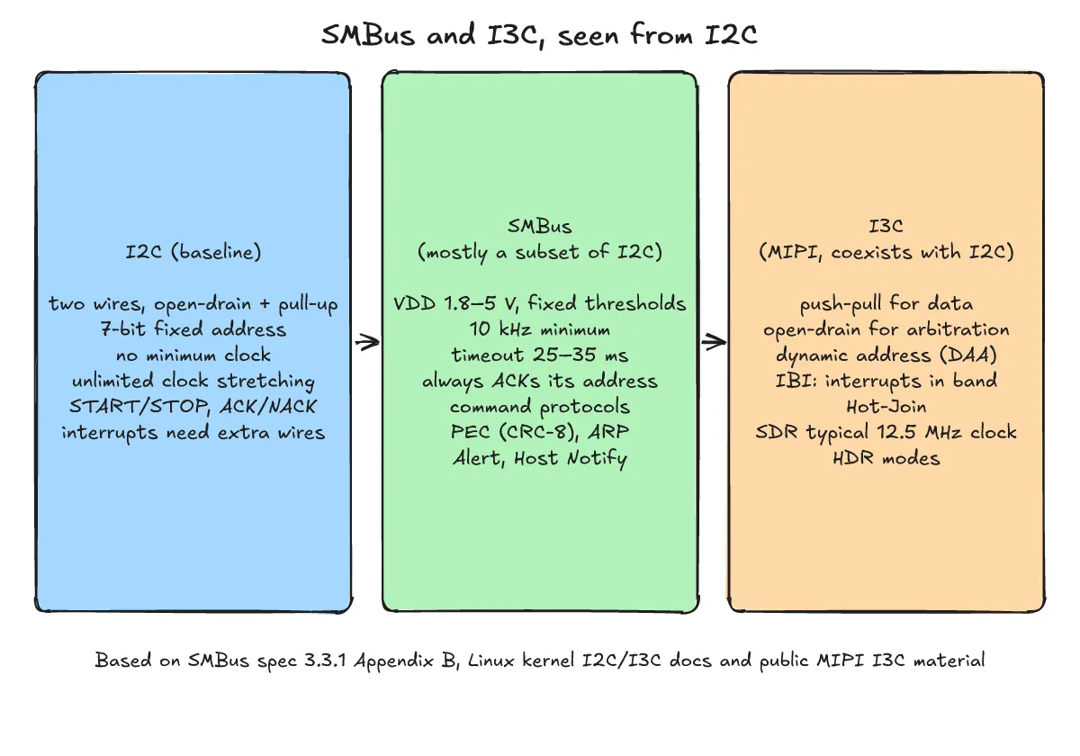
According to the Linux kernel documentation, SMBus is based on the I2C protocol and is mostly a subset of I2C protocols and signaling. Many I2C devices work on an SMBus and the two are generally interoperable, but SMBus adds protocol semantics and electrical and timing rules beyond what is required for I2C branding. Consequently, some systems do not meet both SMBus and I2C electrical constraints, and some devices cannot implement all common SMBus protocol semantics or messages.
MIPI I3C is a MIPI-standardized protocol designed to overcome I2C limitations while remaining power-efficient. As listed in the MIPI I3C FAQ and Linux kernel I3C documentation, those legacy I2C limitations include a fixed 7-bit address, no in-band interrupts (requiring extra wires), limited data rates, no automatic discovery of connected devices, and targets stretching the clock potentially hanging the system. An I3C bus can hold both I3C devices and legacy I2C targets on the same two wires.
How does SMBus differ electrically from I2C?
One-line answer: SMBus restricts supply voltage to 1.8 V–5 V and defines fixed input thresholds (VIL 0.8 V, VIH 1.35 V), a 10 kHz minimum clock frequency, three speed classes (100 kHz, 400 kHz, 1 MHz), and a Low Power class.
Appendix B and Table 2 of the SMBus Specification 3.3.1 note that while SMBus and I2C are very similar and generally interoperable, they differ in voltage levels, clock bounds, and power classes.
Supply voltage (VDD) and input thresholds (VIL, VIH)
SMBus restricts nominal supply voltage (VDD) to a minimum of 1.8 V and a maximum of 5 V. Whereas I2C scales its input thresholds with supply voltage (VIL = 30% of VDD and VIH = 70% of VDD), SMBus specifies fixed input thresholds of VIL = 0.8 V and VIH = 1.35 V. Over the SMBus supply voltage range, I2C and SMBus devices are generally interoperable.
Clock frequency range and Low Power class
The I2C specification defines no minimum clock frequency, whereas SMBus requires a minimum operating frequency (fSMB) of 10 kHz and organizes maximum bus speeds into three speed classes: 100 kHz, 400 kHz, and 1 MHz. In addition, SMBus defines a Low Power class, while I2C has no similar specification.
| Parameter | I2C | SMBus (Spec 3.3.1) |
|---|---|---|
Nominal supply voltage (VDD) | No SMBus-style range limit | 1.8 V min to 5 V max |
Input thresholds (VIL / VIH) | 30% of VDD / 70% of VDD | Fixed 0.8 V / 1.35 V |
| Minimum clock frequency | No minimum | 10 kHz |
| Speed classes / range | Typically up to 400 kHz, high speed up to 5 MHz | 100 kHz / 400 kHz / 1 MHz (three classes) |
| Low Power specification | None | Low Power class defined |
Why does SMBus have a timeout and how does it work?
One-line answer: To prevent a target from holding the clock low indefinitely and hanging the bus, SMBus enforces a clock-low timeout tTIMEOUT of 25–35 ms, limits cumulative clock extension, and requires devices to acknowledge their own address.
tTIMEOUT (25–35 ms) and clock-low extension limits
In I2C, a target is allowed to hold the clock line low (clock stretching) for an unlimited time. SMBus not only sets a 10 kHz minimum clock frequency, but also limits cumulative clock-low extension per byte by the controller and per message by the target.
SMBus also defines a clock-low timeout tTIMEOUT with a minimum of 25 ms and a maximum of 35 ms (Table 2 and §4.2.2). After tTIMEOUT, the bus is presumed hung: any device that detects a single clock held low longer than tTIMEOUT,MIN (25 ms) should release the bus, and all devices must reset their I/O interface and be ready to accept a new START condition no later than tTIMEOUT,MAX (35 ms).
Mandatory address ACK and command-oriented protocols
SMBus requires a device to always acknowledge (ACK) its own address, with limited exceptions, so that the host can distinguish a failed or removed device; I2C does not require this.
Furthermore, while I2C specifies only how bytes move on the wire, SMBus defines command-oriented protocols. Examples include Quick Command (sending one bit in the Rd/Wr position), Receive Byte, Read/Write Byte, Read/Write Word, Process Call, and Block Read/Write (transferring up to 32 bytes along with a count byte). Not all I2C devices implement all SMBus protocols, and SMBus read transactions generally use a REPEATED START (Sr), which some I2C devices may not understand.
What is PEC and how is it calculated?
One-line answer: Packet Error Checking (PEC) is a CRC-8 byte calculated with polynomial C(x) = x^8 + x^2 + x^1 + 1 (0x07) over every message byte—including addresses and R/W bits—and appended immediately before the terminating STOP.
PEC (CRC-8) rules and Python computation example
Introduced in SMBus Revision 1.1 (§6.4 of the specification), PEC appends a CRC-8 error-checking byte immediately before the terminating STOP. The CRC-8 is calculated over all message bytes—including address and read/write bits—using the polynomial C(x) = x^8 + x^2 + x^1 + 1, and is appended by whichever device supplied the last data byte. Every SMBus protocol except Quick Command and Host Notify has both a with-PEC variant and a without-PEC variant; PEC is optional for general transfers but required during ARP.
The following script, smbus_pec.py, is a pure Python 3.13 computation of the SMBus PEC CRC-8 over example bytes (address 0x50, command 0x10, data 0xAB) with no hardware or bus traffic involved (cross-checked against a second bit-serial implementation that produced identical values):
# SMBus PEC = CRC-8, polynomial x^8 + x^2 + x + 1 (0x07), over every message byte
# including the address+R/W bytes. Example values only (address 0x50, command 0x10, data 0xAB).
def crc8(data, poly=0x07):
    crc = 0
    for byte in data:
        crc ^= byte
        for _ in range(8):
            crc = ((crc << 1) ^ poly) & 0xFF if crc & 0x80 else (crc << 1) & 0xFF
    return crc

def hexs(bs):
    return " ".join(f"{b:02X}" for b in bs)

print(f"check value crc8(b'123456789') = 0x{crc8(b'123456789'):02X}")

addr = 0x50
write_byte = [addr << 1 | 0, 0x10, 0xAB]               # S Addr+Wr, Command, Data
pec = crc8(write_byte)
print(f"Write Byte bytes: {hexs(write_byte)} -> PEC 0x{pec:02X}")

read_byte = [addr << 1 | 0, 0x10, addr << 1 | 1, 0xAB]  # Addr+Wr, Command, Sr Addr+Rd, Data
print(f"Read Byte bytes:  {hexs(read_byte)} -> PEC 0x{crc8(read_byte):02X}")

received = write_byte[:2] + [write_byte[2] ^ 0x01]      # one bit flipped in the data byte
print(f"received {hexs(received)} with PEC 0x{pec:02X}: "
      f"recomputed 0x{crc8(received):02X} -> {'OK' if crc8(received) == pec else 'mismatch'}")
Running python3 smbus_pec.py produces:
check value crc8(b'123456789') = 0xF4
Write Byte bytes: A0 10 AB -> PEC 0x47
Read Byte bytes:  A0 10 A1 AB -> PEC 0x08
received A0 10 AA with PEC 0x47: recomputed 0x40 -> mismatch
In line 1, 0xF4 is the known check value for this CRC-8 over the string "123456789", serving as a self-check of the implementation. In line 2, the Write Byte example bytes A0 10 AB (where A0 is address 0x50 shifted left with Wr=0) yield a PEC of 0x47. In line 3, the Read Byte example includes the repeated-start address byte A1 (A0 10 A1 AB), producing a different PEC of 0x08. In line 4, flipping a single bit in the data byte (A0 10 AA) changes the recomputed PEC to 0x40, which does not match 0x47 (mismatch)—showing how the receiver detects a transmission error. The address, command, and data bytes are arbitrary example values.
ARP (address 0x61), SMBus Alert, Host Notify, and kernel driver rules
Beyond PEC, SMBus defines mechanisms for address assignment, interrupt signaling, and Linux kernel driver portability:
- ARP (Address Resolution Protocol): Introduced in Revision 2.0, ARP adds device enumeration and dynamic address assignment. All ARP communications use address
0x61and require PEC checksums. - SMBus Alert and SMBus Host Notify: Introduced in Revision 1.0, SMBus Alert lets several devices share a single interrupt line on the host while allowing the host to learn which device triggered it. With SMBus Host Notify, a target acting as controller sends a message to the host in the same form as
Write Word, replacing the command code with the alerting device’s address. - Linux kernel driver guidance: The Linux kernel documentation advises that if a device uses only the SMBus subset, its driver should use SMBus commands so it works on both SMBus adapters and I2C adapters—the SMBus command set is automatically translated to I2C on I2C adapters, whereas plain I2C commands cannot be handled at all on most pure SMBus adapters. Drivers should also check per-transaction functionality flags such as
I2C_FUNC_SMBUS_READ_BLOCK_DATA.
How does I3C differ from I2C?
One-line answer: MIPI I3C keeps a two-wire interface while adding Dynamic Address Assignment (DAA), In-Band Interrupts (IBI) without extra signals, Hot-Join, Common Command Codes (CCC), a 12.5 MHz typical SDR clock (11.1 Mbps typical), and HDR modes up to 100 Mbps.
Dynamic Address Assignment (DAA) with BCR, DCR, and 48-bit Provisioned ID
Every I3C device on an I3C bus must be assigned a dynamic address before normal communication begins. Discovery and assignment take place through DAA (Dynamic Address Assignment), during which each device reports an 8-bit BCR (Bus Characteristics Register), an 8-bit DCR (Device Characteristics Register), and a 48-bit Provisioned ID. I3C also uses the broadcast address 7'h7E; because 7'h7E is reserved in I2C, legacy I2C targets on the same bus never match it.
In-Band Interrupts (IBI) and Hot-Join
With In-Band Interrupts (IBI), targets generate interrupts directly over the two bus wires without needing an external interrupt signal, reducing signal wire count. If two devices interrupt at the same time, the lower dynamic address wins arbitration and takes higher priority. Controllers can also inhibit interrupts, and Hot-Join allows devices to join the bus after initial bus configuration.
CCC commands and SDR/HDR transfer speeds
I3C defines Common Command Codes (CCC) with an 8-bit ID where bit 7 = 0 indicates a broadcast command to all targets and bit 7 = 1 indicates a direct command to a specific target. For normal private SDR (Single Data Rate) transfers, the Linux kernel documentation notes a typical clock frequency of 12.5 MHz, and the MIPI overview page cites a typical data rate of 11.1 Megabits per second (Mbps) with higher-performance High Data Rate (HDR) modes up to 100 Mbps (the kernel documentation lists HDR-DDR, HDR-TSP, and HDR-TSL; the MIPI overview page mentions HDR-DDR and HDR-BT in I3C Basic v1.1.1). MIPI I3C Basic is a public subset available without membership.
Why does I3C mix push-pull and open-drain modes?
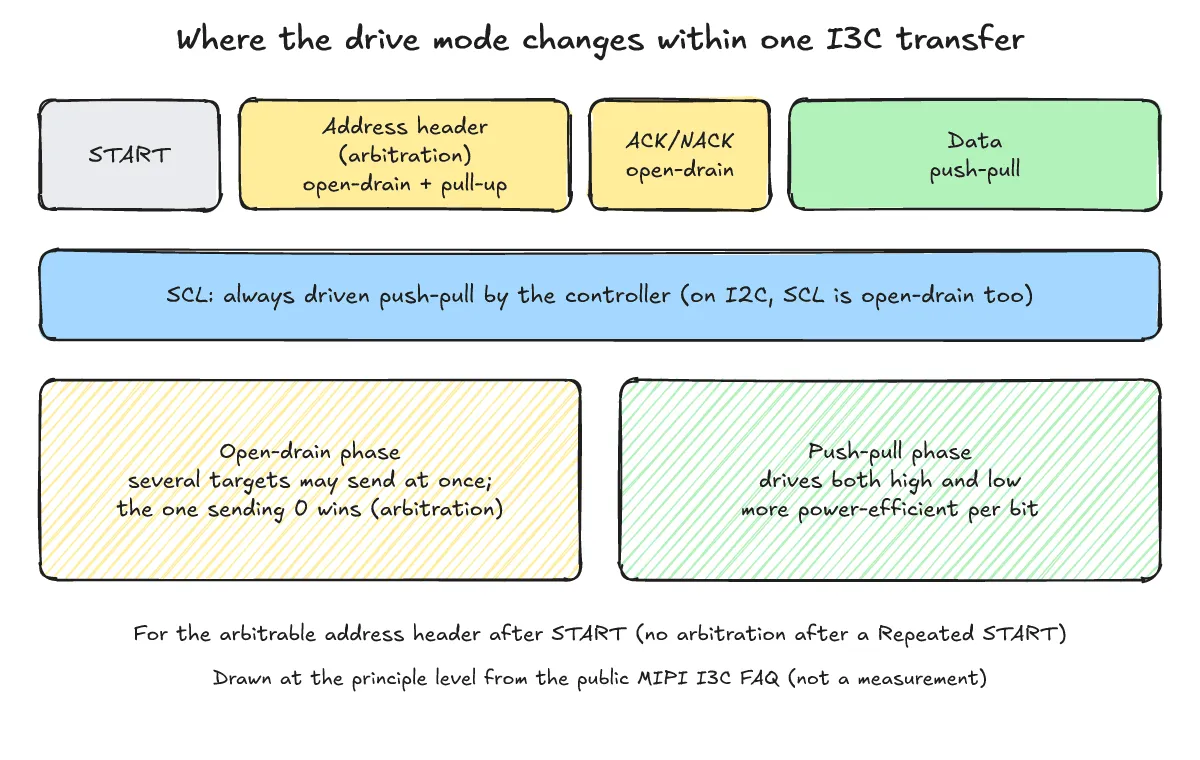
One-line answer: I3C reverts to open-drain right after a START so multiple targets can arbitrate on the address header, then uses push-pull for data transfers and SCL clock driving to achieve high data rates and better per-bit power efficiency.
Open-drain address arbitration and push-pull data/SCL driving
As explained in the MIPI I3C FAQ, the I3C bus uses push-pull mode for data transfers. Right after a START (an initial START, not a Repeated START), the bus reverts to open-drain mode and the controller enables the open-drain class pull-up; in this arbitrable address header phase, a target driving a low value (logic 0) wins arbitration.
In addition, the controller always drives SCL in push-pull mode, unlike legacy I2C where SCL uses open-drain. Actively driving both SCL and SDA in push-pull rather than open-drain makes per-bit power consumption more efficient as well.
Coexistence with legacy I2C targets
When operating in open-drain mode or addressing legacy I2C targets on the same bus, the controller uses the open-drain pull-up. According to the Linux kernel I3C documentation, legacy I2C devices on an I3C bus should have 50 ns spike filters to operate efficiently, and because I2C devices cannot be discovered automatically via DAA, they must be statically declared along with LVR (Legacy Virtual Register) information.
Where are SMBus and I3C typically used?
One-line answer: SMBus is used for system and power management, batteries, sensors, and inventory EEPROMs, while MIPI I3C is used for sensors, server system management, memory sideband, debug, and power management.
According to §1.3 of the SMBus Specification 3.3.1, SMBus is used for system and power management, rechargeable battery management, sensors, and inventory EEPROMs. According to the MIPI I3C specification overview page, I3C is used for connecting sensors, server system management, memory sideband, debug, and power management.
Both SMBus and I3C are also used as physical transports (bindings) for higher-level server management protocols; for details on how management packets, EIDs, and transport bindings work, see What are MCTP and PLDM? Server device management and how MCTP packets, EIDs and bindings work.
What are the frequently asked questions?
One-line answer: Here are concise answers on using SMBus commands across Linux kernel adapters, when PEC is required, and what legacy I2C devices need on an I3C bus.
Can the same Linux driver work on both SMBus adapters and I2C adapters?
Yes, if the device uses only the SMBus subset and the driver is written with SMBus commands. In the Linux kernel, the SMBus command set is automatically translated to I2C on I2C adapters, whereas plain I2C commands cannot be handled on most pure SMBus adapters; drivers should check functionality flags such as I2C_FUNC_SMBUS_READ_BLOCK_DATA.
Is the PEC (CRC-8) byte always mandatory in SMBus?
No. Every SMBus protocol except Quick Command and Host Notify has both a with-PEC and a without-PEC variant, making PEC optional for general device transfers. However, PEC checksums are mandatory during ARP (Address Resolution Protocol) communications at address 0x61.
What is required to connect legacy I2C devices to an I3C bus?
Legacy I2C devices cannot be discovered dynamically through DAA, so they must be statically declared with their LVR information and should include a 50 ns spike filter to be efficient. The controller uses the open-drain pull-up when addressing them, and the I3C broadcast address 7'h7E is reserved in I2C so legacy I2C targets never match it.
What related posts are worth reading?
One-line answer: These related posts cover serial bus basics, open-drain versus push-pull outputs, and higher-level server management transport bindings.
- I2C, SPI and UART basics
- What are MCTP and PLDM? Server device management and how MCTP packets, EIDs and bindings work
- “What is the difference between open-drain and push-pull? Why pull-up and pull-down resistors are needed”
What are the sources?
One-line answer: This post is based on the SMBus 3.3.1 specification, the Linux kernel I2C, SMBus, and I3C documentation, and the public MIPI I3C specification resources listed below.
- System Management Bus (SMBus) Specification Version 3.3.1 (checked 2026-11-04)
- Linux kernel docs: Introduction to I2C and SMBus (checked 2026-11-04)
- Linux kernel docs: The SMBus Protocol (checked 2026-11-04)
- Linux kernel docs: I3C protocol (checked 2026-11-04)
- MIPI I3C specification overview (checked 2026-11-04)
- MIPI I3C v1.2 & I3C Basic v1.2 FAQ (public release edition) (checked 2026-11-04)