PLDM (Platform Level Data Model) is a DMTF standard that uses the PLDM type field in its message header to group management functions such as base discovery, platform monitoring (PDRs and sensors), PLDM firmware update, and RDE. Based on the DMTF DSP0240 PLDM Base Specification 1.2.1 and the companion specifications for each type, this post summarizes the common PLDM header structure, the roles of Types 0, 2, 5, and 6, and the firmware update sequence.
Summary
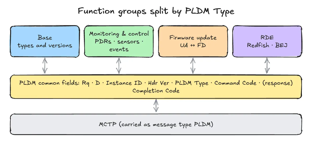
PLDM divides its function groups using the “PLDM Type” field in the message header. Type 0 Base provides basic commands to ask which types and versions an endpoint can handle; Type 2 monitoring and control covers PDRs (Platform Descriptor Records) and sensor readings; Type 5 handles firmware updates; and Type 6 RDE enables managing a device using Redfish. A firmware update starts when the Update Agent (UA) sends RequestUpdate, continues as the Firmware Device (FD) pulls chunks of the image with RequestFirmwareData, and finishes with ActivateFirmware.
What does a PLDM message look like?
One-line answer: A PLDM message begins with a common header containing request and instance fields, a PLDM Type identifying the function group, and a PLDM Command Code (plus a PLDM Completion Code in responses).
DSP0240 1.2.1 defines the following common fields in the PLDM message header:
| Field Name | Meaning |
|---|---|
Rq | Distinguishes whether the message is a request or a response. |
D | Indicates whether the message is a datagram. |
Instance ID | Identifies the instance to match requests with responses or asynchronous messages. |
Hdr Ver | Indicates the PLDM header version. |
PLDM Type | Identifies the PLDM function group (type) of the message. |
PLDM Command Code | Specifies the command within the given PLDM Type. |
PLDM Completion Code | Present in responses only; indicates the completion status of the command. |
DSP0240 notes that PLDM type values themselves are defined in DMTF DSP0245. PLDM rides on top of MCTP as an MCTP message type; the underlying MCTP transport header and EIDs are covered in “What are MCTP and PLDM? Server device management and how MCTP packets, EIDs and bindings work” (previous in series).
What does Type 0 Base do?
One-line answer: Type 0 Base provides foundational commands to check which PLDM types, versions, and commands an endpoint can handle and to query its TID.
Type 0 (PLDM_BASE, 0x00) defines the basic discovery commands used to inspect an endpoint’s capabilities. Its commands include GetPLDMTypes (command code 0x4 per libpldm’s base.h), GetPLDMVersion, GetPLDMCommands, and GetTID.
In “How are MCTP and PLDM handled on Linux? AF_MCTP sockets, mctp, mctpd, libpldm and pldmd” (next in series), a GetPLDMTypes request is encoded using libpldm (without sending it over MCTP), producing the following three bytes and field summary:
encode_get_types_req rc=0 len=3 bytes: 81 00 04
request=1 instance_id=1 header_ver=0 pldm_type=0 command=0x04
As stated on the second line of the output, the encoded bytes 81 00 04 represent request=1, instance_id=1, header_ver=0, pldm_type=0, and command=0x04.
What are PDRs and sensors in Type 2 monitoring?
One-line answer: PDRs (Platform Descriptor Records) are records that describe a platform’s entities and sensors, and Type 2 commands read those records, sensor values, and platform events.
DSP0248 1.4.0 (PLDM for Platform Monitoring and Control) defines the core concepts used in Type 2 (PLDM_PLATFORM, 0x02):
- PDR (Platform Descriptor Record) and PDR repository: PDRs describe the entities and sensors on a platform and are stored in a PDR repository (the Primary PDR Repository). The
GetPDRcommand reads records from this repository. - Sensor PDR types and readings: Sensor descriptors include
Numeric Sensor PDRfor numeric measurements andState Sensor PDRfor discrete states, whileGetSensorReadingretrieves current sensor values. - Event reporting: The
PlatformEventMessagecommand is used to report platform events.
In what order does a Type 5 firmware update proceed?
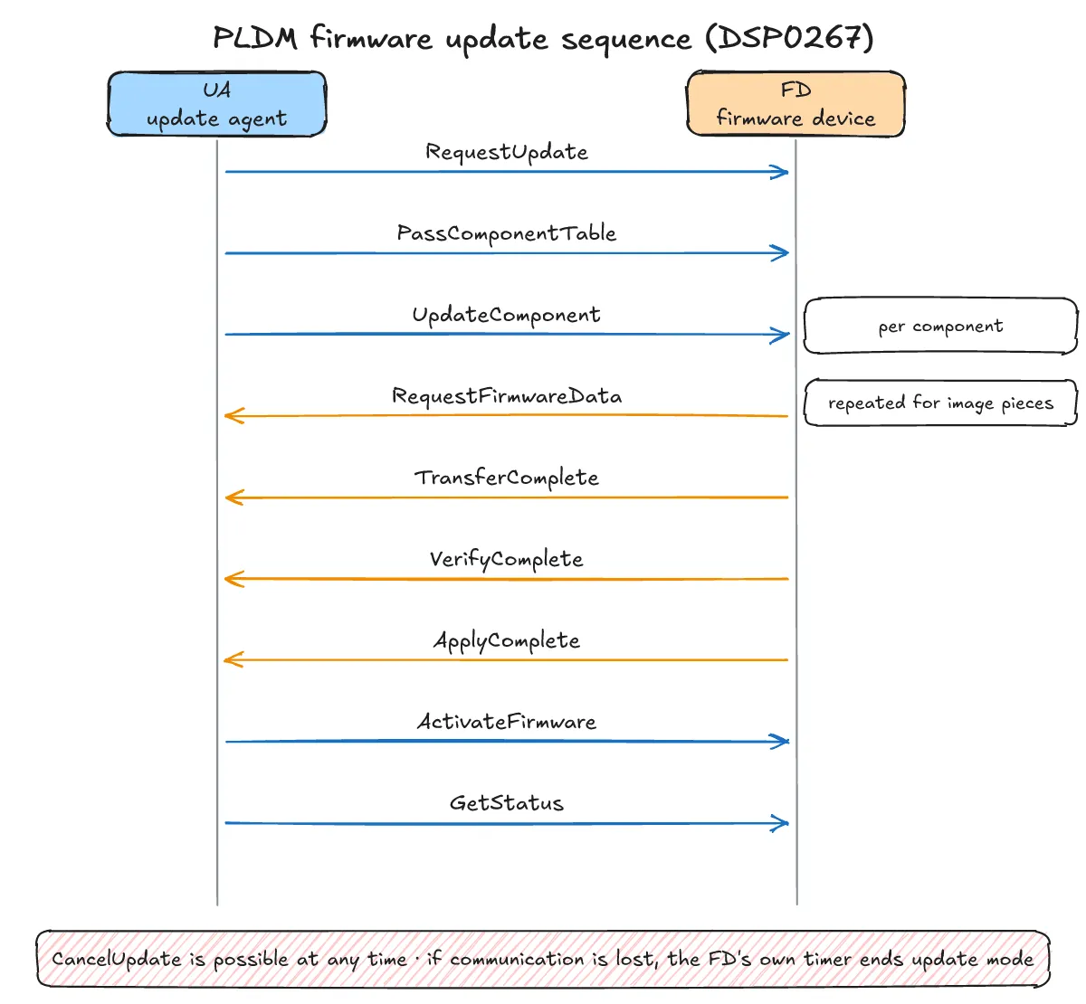
One-line answer: The Update Agent (UA) initiates the update, the Firmware Device (FD) pulls image pieces and reports transfer, verification, and application completion, and the UA finishes with activation.
According to Figure 1 of DSP0267 1.3.0 (PLDM for Firmware Update), a Type 5 (PLDM_FWUP, 0x05) PLDM firmware update between an Update Agent (UA) and a Firmware Device (FD) proceeds in the following order:
- The UA sends
RequestUpdateto the FD, and the FD enters update mode. - (Optional) Package data and metadata are exchanged.
- The UA sends
PassComponentTableto pass component information to the FD. - For each component, the UA sends
UpdateComponent; the FD requests pieces of the image usingRequestFirmwareData, sendsTransferCompletewhen the transfer finishes, sendsVerifyCompleteafter verification, and sendsApplyCompleteafter applying the image. - When all components are processed, the UA sends
ActivateFirmwareto the FD and checks completion withGetStatus. Components that cannot self-activate remain pending until an external reset or similar action occurs. CancelUpdatecan be sent at any time to abort the update; if communication is lost, the FD exits update mode according to its own internal timer.
What does Type 6 RDE do?
One-line answer: Type 6 RDE lets the device side handle Redfish data using BEJ (Binary Encoded JSON) and dictionaries.
Defined in DSP0218 1.2.0 (“PLDM for Redfish Device Enablement”), Type 6 (PLDM_RDE, 0x06) enables a device to handle Redfish data. To represent Redfish data compactly in binary form, RDE uses BEJ (Binary Encoded JSON) together with a dictionary.
What are the frequently asked questions?
One-line answer: Here are answers on where PLDM type numbers are defined, how interrupted firmware updates behave, and what other PLDM types exist.
Where are PLDM type numbers defined?
DSP0240 refers to DMTF DSP0245 for PLDM type values. The type numbers 0, 2, 5, and 6 used in this post come from the enum in OpenBMC libpldm’s base.h (PLDM_BASE 0x00, PLDM_PLATFORM 0x02, PLDM_FWUP 0x05, PLDM_RDE 0x06).
What happens if a firmware update fails midway?
Per DSP0267, CancelUpdate can be used at any time, and if communication is lost, the FD’s own internal timer ends update mode.
What are the SMBIOS, BIOS, and FRU types?
In addition to the types covered here, libpldm’s base.h also lists 0x01 SMBIOS, 0x03 BIOS, and 0x04 FRU (as well as 0x07 FILE).
What related posts are worth reading?
One-line answer: See the previous post in this series on MCTP packets, EIDs, and bindings, and the next post on Linux sockets, tools, and libraries.
- “What are MCTP and PLDM? Server device management and how MCTP packets, EIDs and bindings work” (previous in series)
- “How are MCTP and PLDM handled on Linux? AF_MCTP sockets, mctp, mctpd, libpldm and pldmd” (next in series)
- What are common MCTP/PLDM interview questions and model answers? 19 Qs on packets, EIDs, Instance IDs, sensors, firmware update and debugging
What are the sources?
One-line answer: This post is based on DMTF PLDM specifications (DSP0240, DSP0248, DSP0267, DSP0218), the OpenBMC libpldm header, and the DMTF PMCI standards page.
- DMTF DSP0240 PLDM Base Specification 1.2.1 (checked 2026-10-31)
- DMTF DSP0248 PLDM for Platform Monitoring and Control 1.4.0 (checked 2026-10-31)
- DMTF DSP0267 PLDM for Firmware Update 1.3.0 (checked 2026-10-31)
- DMTF DSP0218 PLDM for Redfish Device Enablement 1.2.0 (checked 2026-10-31)
- openbmc/libpldm — include/libpldm/base.h (checked 2026-10-31)
- DMTF PMCI Standards (checked 2026-10-31)