When preparing model answers to technical MCTP and PLDM questions, it helps to connect core topics—MCTP EIDs and packet assembly, PLDM Instance IDs, sensor thresholds and hysteresis, PLDM firmware update, and OpenBMC pldmd—directly to their specification numbers. Based on the DMTF PMCI standards, this post provides concise, specification-backed model answers to 19 common technical questions.
Summary
Most MCTP/PLDM questions fall into five groups: MCTP packets and addressing (EIDs and tags), PLDM common rules (TID and Instance ID), monitoring (sensors, thresholds, and events), firmware update (Type 5 sequence), and the layer-by-layer order for debugging a missing response. Citing the underlying specification numbers (DSP0236, DSP0240, DSP0248, DSP0267) makes each answer much stronger.
What questions come up in MCTP/PLDM interviews?
One-line answer: They fall into five groups: MCTP transport, PLDM Base common rules, monitoring (sensors and events), firmware update, and layer-by-layer debugging (including the link to OpenBMC and Redfish).
The 19 questions are organized by topic group as follows:
| Group | Questions and Core Topics |
|---|---|
| MCTP transport | Q1–Q8 (medium independence, roles, SOM/EOM/Pkt Seq, Msg Tag/TO, MCTP EIDs, bindings, Control messages) |
| PLDM Base common rules | Q9–Q11 (discovery commands, PLDM Instance ID and retries, timing PN1 and PT1–PT4) |
| PLDM monitoring (sensors and events) | Q12–Q15 (numeric vs. state sensors, sensor threshold hysteresis, event reporting, PDR repository) |
| PLDM firmware update | Q16–Q17 (Type 5 sequence, failure and abort handling) |
| Layer-by-layer debugging | Q18 (bottom-up check from bus to MCTP, PLDM, and application service) |
| OpenBMC and Redfish link | Q19 (AF_MCTP, mctpd, libpldm, OpenBMC pldmd, bmcweb, Type 6 RDE) |
How do you answer MCTP transport questions?
One-line answer: Explain medium independence, packet assembly with SOM/EOM/Pkt Seq, Msg Tag and TO bits, MCTP EID assignment, and transport binding differences based on DSP0236.
Q1. Why does the BMC manage devices with MCTP/PLDM requests and responses instead of reading device memory directly?
- MCTP is medium-independent: it uses the same message format over SMBus/I2C, I3C, and PCIe VDM, so management software does not have to be rewritten per bus.
- If register layouts differ per device, the BMC would need a per-device map; with PLDM, the device describes itself with PDRs and the BMC asks with standard commands (
GetPDR,GetSensorReading), so adding a device changes BMC code less. - Request/response messages carry an explicit Completion Code, so success, failure, or an unsupported command come back clearly.
Basis: DSP0236, DSP0240, DSP0248
Q2. What are the respective roles of MCTP and PLDM?
- 30-second answer: MCTP handles transport, addressing (EID), and packet split/reassembly, while PLDM defines the management messages carried on top (sensors, firmware update, and more).
- MCTP message type
0x01is PLDM (0x00is MCTP Control, and0x04is NVMe-MI). - For full details, see What are MCTP and PLDM? Server device management and how MCTP packets, EIDs and bindings work and What are PLDM types? Base, monitoring (PDRs and sensors), firmware update and RDE.
Basis: DSP0236, DSP0239
Q3. How does MCTP split large messages into packets and reassemble them?
- The header includes
SOM(start) andEOM(end) bits;SOM=1andEOM=1indicates a single-packet message that needs no reassembly. - The baseline transmission unit is 64 bytes.
- The receiver starts assembly only on a
SOMpacket; middle or end packets without a precedingSOMare silently dropped, and a newSOMduring assembly discards the in-progress assembly and starts again.
Basis: DSP0236 8.7–8.9
Q4. Why is Pkt Seq 2 bits wide and what does it detect?
- It increments modulo 4 per packet in a multi-packet message, allowing the receiver to detect up to three successive missing packets.
- An unexpected sequence number terminates assembly; MCTP does not use out-of-order packets for message assembly.
Basis: DSP0236 header field table, 8.9
Q5. Why are the Message Tag and Tag Owner (TO) bit needed?
Msg Tag(3 bits) distinguishes several messages in flight with the same peer;TOand the tag stay the same fromSOMtoEOM.TO=1means “I originated this tag (requester side)”; the responder returns the same tag value withTO=0.- A
TO=0packet with a tag the receiver did not issue or no longer expects is dropped (“Bad, unexpected, or expired message tag”).
Basis: DSP0236 header field table, 8.7
Q6. Who assigns EIDs and how?
- The bus owner manages MCTP EID assignment:
Set Endpoint ID(0x01) assigns an EID, andGet Endpoint ID(0x02) checks it. EID 0is the null EID, and0xFFis the broadcast EID (reserved).
Basis: DSP0236
Q7. How do the SMBus/I2C, I3C and PCIe VDM bindings differ?
- SMBus/I2C binding (DSP0237): MCTP packets use SMBus command code
0x0F; for serial bus basics, see I2C vs SPI vs UART: How to Compare Them in an Embedded Interview. - I3C binding (DSP0233): target-to-controller transfer has IBI (In-Band Interrupt) mode and polling mode, and the target must provide both.
- PCIe VDM binding (DSP0238): uses DMTF Vendor ID
1AB4hand routing typesRoute to Root Complex,Route by ID, andBroadcast from Root Complex.
Basis: DSP0237, DSP0233, DSP0238
Q8. When are MCTP Control messages used?
- Common discovery and configuration commands include
Set Endpoint ID(0x01),Get Endpoint ID(0x02),Get Endpoint UUID(0x03),Get MCTP Version Support(0x04), andGet Message Type Support(0x05). - A natural flow is to first check with
Get Message Type Supportwhether the device supports PLDM (0x01), then move on to PLDM commands.
Basis: DSP0236, DSP0239
How do you answer PLDM Base common-rule questions?
One-line answer: Explain initial discovery commands (GetTID, GetPLDMTypes, GetPLDMVersion, GetPLDMCommands), the 5-bit PLDM Instance ID retry rules, and timing parameters (PN1, PT1–PT4) based on DSP0240.
Q9. What do you query first when meeting a PLDM device?
GetTID(0x02) for the Terminus ID (SetTIDis0x01).GetPLDMTypes(0x04) for the types it supports (0Base,2platform monitoring and control,5firmware update,6RDE).GetPLDMVersion(0x03) andGetPLDMCommands(0x05) for per-type versions and commands; see What are PLDM types? Base, monitoring (PDRs and sensors), firmware update and RDE for type details.
Basis: DSP0240, libpldm base.h
Q10. What is the PLDM Instance ID and how does it relate to retries?
- It is a 5-bit value that pairs a request with its response; the response carries the same PLDM Instance ID.
- Retries reuse the same Instance ID, and a new Instance ID is used only after retries for that request are finished.
- A responder that already processed a request successfully and receives it again with the same Instance ID does not execute it again and returns
SUCCESS; PLDM responses themselves are not retried (DSP0240 also lists “Bad Instance ID”).
Basis: DSP0240
Q11. How do you explain PLDM timing (PN1 and PT1–PT4)?
PN1request retries: minimum 2 (a minimum of three tries in total: the original try plus two retries), all withinPT3max of the initial request.PT1request-to-response time: max 100 ms;PT4transmission delay: max 100 ms;PT3Instance ID expiration interval: min 5 s, max 6 s.PT2(the time a requester waits before retrying) is not a single number but a range derived fromPT1,PT3, andPT4.
Basis: DSP0240 1.2.1 Table 6
How do you answer PLDM monitoring (sensor and event) questions?
One-line answer: Cover numeric vs. state sensors, upper/lower thresholds and sensor threshold hysteresis on recovery transitions, event messages vs. polling, and self-describing PDRs based on DSP0248.
Q12. How do numeric sensors and state sensors differ?
- Numeric sensors read a value such as temperature or voltage with
GetSensorReading(0x11) and are described by aNumeric Sensor PDR. - State sensors report one of a defined set of states with
GetStateSensorReadingsand are described by aState Sensor PDR.
Basis: DSP0248, libpldm platform.h
Q13. How do thresholds and hysteresis work?
- Upper and lower thresholds each have
warning,critical, andfatallevels, orderedlower fatal < … < upper fatal, and are read or written withGetSensorThresholds(0x12) andSetSensorThresholds(0x13). - Sensor threshold hysteresis is subtracted from the upper thresholds and added to the lower thresholds; it applies only on the transition from a more severe to a less severe state, keeping the state from flickering near a boundary (commands
GetSensorHysteresis0x15andSetSensorHysteresis). EventStateincludes the effect of hysteresis, whereasPresentStatedoes not.
Basis: DSP0248
Q14. How are device events received: polling or PlatformEventMessage?
- The terminus can send events to the event receiver with
PlatformEventMessage(0x0A). - The receiver can also fetch queued events with
PollForPlatformEventMessage. - Receiving events only on changes rather than reading sensors every time can reduce bus traffic.
Basis: DSP0248
Q15. Why is the PDR repository needed?
- 30-second answer: It is a collection of records (PDRs) by which the device describes its sensors, effecters, and entities, fetched with
GetPDR(0x51). - The BMC learns from PDRs which sensor ID to read and in which unit, tying back to Q1; for details, see What are PLDM types? Base, monitoring (PDRs and sensors), firmware update and RDE.
Basis: DSP0248
How do you answer PLDM firmware update questions?
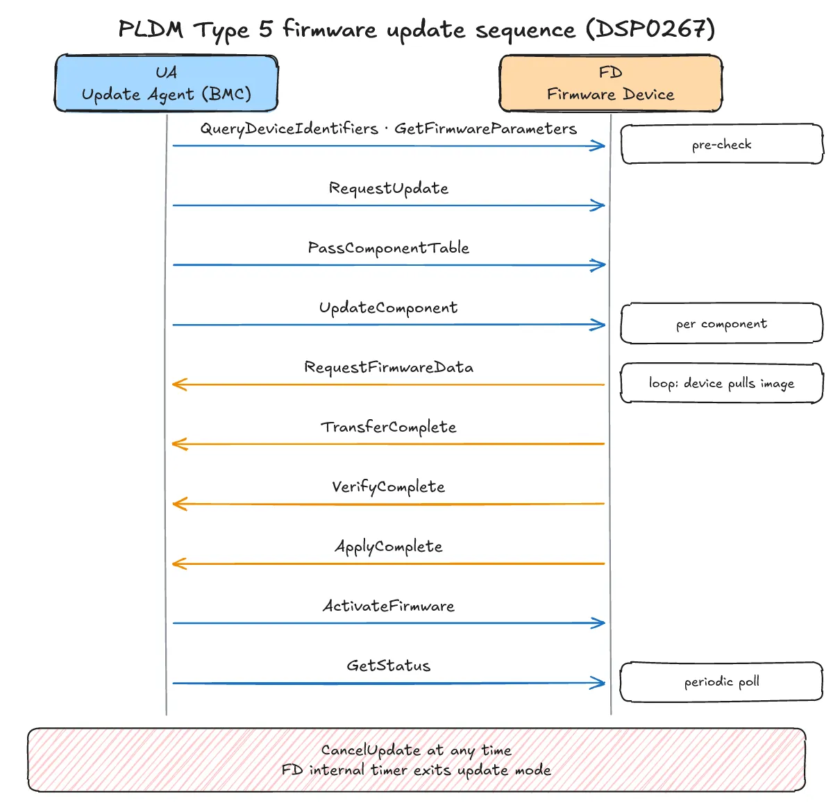
One-line answer: Describe the UA and FD roles, the PLDM firmware update sequence where the FD pulls image data via RequestFirmwareData, and abort handling via CancelUpdate/CancelUpdateComponent and the FD internal timer based on DSP0267.
Q16. In what order does a PLDM Type 5 firmware update proceed?
- Roles: UA (Update Agent, typically the BMC) and FD (Firmware Device). Before starting,
QueryDeviceIdentifiers(0x01) andGetFirmwareParameters(0x02) identify the device and current versions. - UA → FD:
RequestUpdate(0x10) → (optional) package data →PassComponentTable(0x13) → per-componentUpdateComponent(0x14). - FD → UA:
RequestFirmwareData(0x15) repeated as the FD pulls the image →TransferComplete(0x16) →VerifyComplete(0x17) →ApplyComplete(0x18). - UA → FD:
ActivateFirmware(0x1A), thenGetStatus(0x1B) to check status periodically; see What are PLDM types? Base, monitoring (PDRs and sensors), firmware update and RDE for an overview.
Basis: DSP0267 1.3.0, libpldm firmware_update.h
Q17. How are failures or aborts handled during a firmware update?
- The UA can cancel the whole update mode with
CancelUpdate(0x1D) or only the current component withCancelUpdateComponent(0x1C). - The FD has an internal timer that ends update mode, so it is not stuck if the UA disappears.
- Check the FD’s current state with
GetStatus, then decide whether to retry or cancel.
Basis: DSP0267
In what order do you say you would debug a missing response?
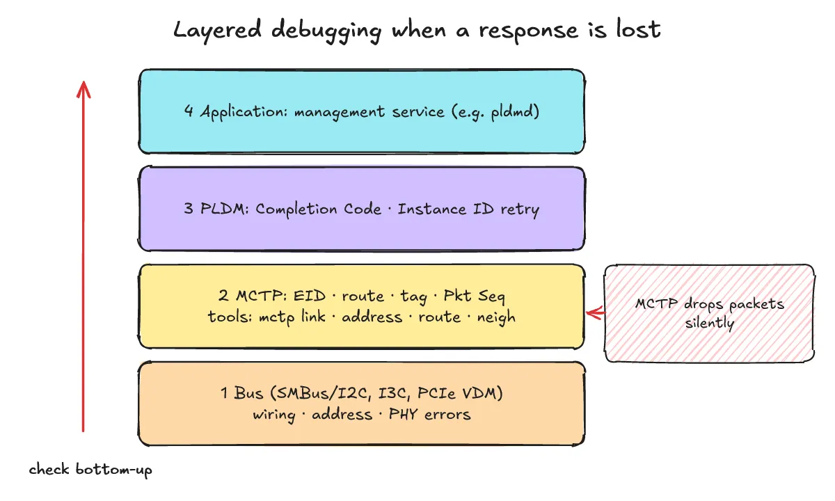
One-line answer: Because MCTP does not report dropped packets, verify from the bottom layer up: physical bus → MCTP (EID, routes, tags, sequence) → PLDM (Completion Code, Instance ID) → upper management service.
Q18. In what order do you debug when no response arrives?
- ① Bus stage: physical-layer errors (data integrity, framing, packet size) drop packets right there, so check wiring, addressing, and bus state first.
- ② MCTP stage: an unroutable EID, a non-matching destination EID, an unsupported header version or transmission unit, a bad tag, or an out-of-order
Pkt Seqare all silently dropped. On a Linux environment where MCTP is available, check interfaces, EIDs, and routes withmctp link,mctp address,mctp route, andmctp neigh(see How are MCTP and PLDM handled on Linux? AF_MCTP sockets, mctp, mctpd, libpldm and pldmd). - ③ PLDM stage: if a response arrives but failed, inspect the Completion Code (
SUCCESS0x00,ERROR0x01,ERROR_INVALID_DATA0x02,ERROR_INVALID_LENGTH0x03,ERROR_NOT_READY0x04,ERROR_UNSUPPORTED_PLDM_CMD0x05,ERROR_INVALID_PLDM_TYPE0x20). If no response arrives at all, check the Instance ID retry and expiration rules (Q10, Q11). - ④ Application stage: only then look at the management service on top (for example,
pldmd). Because the base MCTP protocol does not handle flow or congestion control and does not notify about dropped packets, always check from the lower layers upward.
Basis: DSP0236 8.7–8.10, DSP0240, libpldm base.h, CodeConstruct/mctp
How do you explain the link to OpenBMC and Redfish?
One-line answer: Over kernel AF_MCTP and mctpd, libpldm and OpenBMC pldmd handle PLDM messages, bmcweb exposes internal services as Redfish APIs, and PLDM Type 6 RDE lets devices exchange Redfish data.
Q19. How does it connect to OpenBMC and Redfish?
- 30-second answer: OpenBMC has the PLDM encode/decode library
libpldmand the OpenBMC PLDM daemonpldmd(openbmc/pldm), while the MCTP side uses the kernelAF_MCTPandmctp/mctpd(CodeConstruct/mctp); see How are MCTP and PLDM handled on Linux? AF_MCTP sockets, mctp, mctpd, libpldm and pldmd. - The
bmcwebREADME describes it as a “DBus to Redfish translator”: data gathered by BMC internal services is exposed externally through the Redfish API. - PLDM Type 6 RDE (DSP0218, “PLDM for Redfish Device Enablement”) lets a device exchange Redfish data using BEJ encoding and a dictionary.
Basis: DSP0218, openbmc/pldm, openbmc/bmcweb, CodeConstruct/mctp
What should you avoid when answering?
One-line answer: Do not make up numbers, timers, or codes that are not in the specification; if unsure, state which specification document you would check.
- Do not guess or invent unstated command codes or timer values.
- Keep silent packet drops at the MCTP transport layer (DSP0236) distinct from explicit Completion Code errors at the PLDM layer (DSP0240).
- When unsure of an exact parameter or field definition, state which specification document you would check: DSP0236 (MCTP Base), DSP0240 (PLDM Base), DSP0248 (Monitoring and Control), or DSP0267 (Firmware Update).
What related posts are worth reading?
One-line answer: Read the companion posts covering MCTP/PLDM fundamentals, PLDM types, Linux sockets and daemons, and embedded serial bus comparisons.
- What are MCTP and PLDM? Server device management and how MCTP packets, EIDs and bindings work
- What are PLDM types? Base, monitoring (PDRs and sensors), firmware update and RDE
- How are MCTP and PLDM handled on Linux? AF_MCTP sockets, mctp, mctpd, libpldm and pldmd
- I2C vs SPI vs UART: How to Compare Them in an Embedded Interview
What are the sources?
One-line answer: This post is based on the DMTF PMCI specifications and official OpenBMC, CodeConstruct, and Linux kernel repositories and documentation.
- DMTF PMCI standards (checked 2026-11-01)
- DSP0236 MCTP Base Specification 1.4.0 (checked 2026-11-01)
- DSP0237 MCTP SMBus/I2C Transport Binding 1.2.0 (checked 2026-11-01)
- DSP0233 MCTP I3C Transport Binding 1.0.1 (checked 2026-11-01)
- DSP0238 MCTP PCIe VDM Transport Binding 1.4.0 (checked 2026-11-01)
- DSP0239 MCTP IDs and Codes 1.12.0 (checked 2026-11-01)
- DSP0240 PLDM Base Specification 1.2.1 (checked 2026-11-01)
- DSP0248 PLDM for Platform Monitoring and Control 1.4.0 (checked 2026-11-01)
- DSP0267 PLDM for Firmware Update 1.3.0 (checked 2026-11-01)
- DSP0218 PLDM for Redfish Device Enablement 1.2.0 (checked 2026-11-01)
- openbmc/libpldm (checked 2026-11-01)
- CodeConstruct/mctp (checked 2026-11-01)
- openbmc/pldm (checked 2026-11-01)
- openbmc/bmcweb (checked 2026-11-01)
- Linux kernel docs, MCTP (checked 2026-11-01)